 Full PDF Text Version
27th October 2005 - Full PDF Text Version
This document is a quick guide of IP Office grounding requirements, based on the IP Office Installation Manual.
Avaya strongly recommend that installers always read the installation manual and follow the instructions before powering on any Avaya equipment.
Any equipment that is damaged due to improper grounding or environmental conditions will not qualify for warranty replacement under Avaya’s terms and conditions.
The Avaya IP Office Installation Manual (40DHB0002USCL Issue 10c issued 11th May 2004) describes with figures the requirements for grounding IP Office properly on pages 43 to 47. This document should be read prior to installation.
Points to remember
Make sure that the Protective Ground (and, when required the, Functional Ground) are well connected.
Confirm that the Ground has a resistance below 5 Ohms and that both the In-Range-Out-Of-Building protectors (IROB's) and the IP Office system are connected to a common good grounding point.
Do not earth the IROB's directly to the DS unit - they both should have leads off to the grounding point. An external assessment of the grounding should be obtained if in doubt.
Confirm that the network is protected and that the electrical supply is stable. An external assessment of the electrical supply should be obtained if in doubt.
If a rack mount system is being used, the rack should be grounded in the same way as the IP Office.
Confirm that ALL external interfaces or phones are protected - Protecting 99% of devices is insufficient as there will still be a possible point of failure that could result in damage to the system and the warranty on the system will have been invalidated.
External devices should preferably be protected with the IROB's recommended by Avaya as these have been proven to be effective with IP Office products.
Confirm that the primary network is protected by grounding. There should also be primary protection (e.g. gas discharge tubes) where the cables enter the building. This also applies to the far end in the case of networked systems.
It is also important to keep internal cables physically separate from external cables, (especially cables on either side of the IROB's), as a current can be induced in a cable running alongside another cable that has been struck by lightning.
Grounding Directions for IP Office
Provision is made for both Protective Ground (earthing) and Functional Ground (earthing).
In addition, where the installation of telephones and/or other standard two wire devices in another building is required, IROB protectors must be fitted.
Protective Ground
A Protective Ground must be permanently fitted to IP Office Analog Trunk 16 modules. Connection of this Protective Ground requires the use of suitable tools and must be made at both ends before connection is made to the telecommunications network.
To connect the Protective Ground:
Attached one end of a #14 AWG (minimum size) solid insulated cable (sleeve must be green/yellow) to the Protective Ground Point. Ensure that the Ground Post securing screw is fully tightened.
Connect the other end of the wire to the approved Protective Ground using a fastening that satisfies local regulations.
Functional Ground
To ensure proper operation of the IP Office equipment, Functional Grounding is required.
Caution:
The Functional Ground is not a Protective Ground.
On some models of the units/expansion modules, there may not be a specific M4 Functional Ground point. Either the Trunk module kit fixing screw or the top cover center fixing screw can be used as a Functional Ground point, as shown on the Installation Manual.
To connect the Functional Ground:
Attach one end of a #14 AWG (minimum) solid insulated cable (sleeve must NOT be green/yellow) to the chosen screw and fully tighten.
Connect the other end of the wire to the approved ground, such as building steel or an earthed metal cold water pipe, using a fastening that satisfies local regulations.
Out of Building Telephone Installations
Installation of telephone and/or other standard two wire devices that are external to the building housing the Avaya IP Office or in another building, require IROB protectors to protect the control unit and device from electrical surges. Only Digital Stations should be used for out of building/external telephones. These must be fitted as follows:
System telephone: two IROB protectors.
Standard telephone: two IROB protectors plus one carbon block protector.
Primary protection must be provided at the point where the cable enters the building. This should be three point protection (tip, ring and ground). Typically this would be gas tube protection provided by the local telephone company. The ground wire must be thick enough to handle all the lines being affected by indirect strike at the same time.
The following diagram provides an overview of the protection requirements for installation of telephones that are external to the building housing the Avaya IP Office.
Caution:
No cabling between buildings can be exposed - cabling between buildings must be carried in suitably earthed ducting, ideally underground.
Three versions of IROBs are available as follows:
146C - Trunks - SAP code 407228923
146E - TDL - SAP code 407568161
IP 400 Phone Barrier Box - SAP code 700293897
Installation of a Contact Closure Adjunct controlled device outside the building requires a 146G Surge Protector - (SCL/8) to protect the control unit from electrical surges.
Install the 146C and 146E IROBs as per the instructions supplied with the IROBs.
Where more than three Avaya IP 400 Phone Barrier boxes are to be used they must be rack mounted (see page 4 for details). Avaya IP 400 Phone Barrier Boxes must only be used in conjunction with Avaya IP 400 Phone 8/16/32 modules.
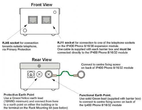
Barrier Box Installation
For standard installation of the Avaya IP400 Phone Barrier Box, follow these directions:
Note:
The following wires
must be kept apart and not routed in the same bundle:
Earth lead from the barrier box to the IP400 Phone 8/16/32 module.
Internal wires, for example wires going directly to the IP400 Phone 8/16/32.
Wires from external telephone going directly to the barrier boxes.
The Avaya IP400 Phone Barrier Box will not connect the ringing capacitor in the UK and other locales, hence a master socket is required.
Caution:
The analogue ports on the front of the IP403 must not be used for lines external to the building.
The Avaya IP400 Phone Barrier Box must not be connected to the analogue trunk lines
Installation of telephones that are external to the building housing the Avaya IP Small Office Edition or IP 406 V2 or in another building require In-Range-Out-Of-Building (IROB) protectors to protect the control unit and device from electrical surges. Only Digital Stations should be used for out of building/external telephones. Two IROB protectors are required.
Rack Mounting Barrier Boxes
Where more than three Avaya IP400 Phone Barrier Boxes are to be used they must be rack mounted.
Rack mounting kits are available (SAP Code 700293905) for mounting up to eight Avaya IP400 Phone Barrier Boxes. A maximum of 16 Avaya IP400 Phone Barrier Boxes (using two Rack kits) can be connected to one IP400 Phone 30 module.
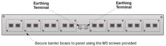
To rack mount up to eight Avaya IP400 Phone Barrier Boxes into a rack, follow these instructions:
Mount the Barrier boxes
in the rack as shown:
For each Barrier Box,
discard the solid green earth wire and connect the green/yellow earth
wire to the Protective Earth Point on the back of the Barrier Box:
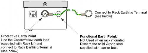
Connect the earth leads:
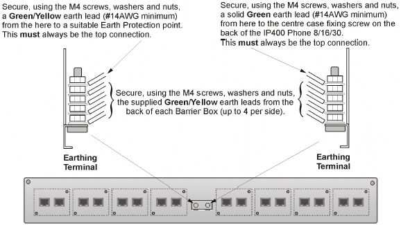
Note:
The following wires must be kept apart, e.g. not routed in the same bundle:
Earth lead from the barrier box to the IP400 Phone 8/16/32 module.
Internal wires, for example wires going directly to the IP400 Phone 8/16/32.
Wires from external telephone going directly to the barrier boxes.
The Avaya IP400 Phone Barrier Box will not connect the ringing capacitor in the UK; hence a Master socket is required.
CAUTION:
The analogue ports on the front of the IP403 must NOT be used for lines external to the building.