Use of ground connections reduces the likelihood of problems in most telephony and data systems. This is especially important in buildings where multiple items of equipment are interconnected using long cable runs, for example phone and data networks.
All IP Office control units and external expansion modules must be connected to a functional ground. Where the unit is connected to a power outlet using a power cord with an earth lead, the power outlet must be connected to a protective earth.
In some cases, such as ground start trunks, in addition to being a protective measure this is a functional requirement for the equipment to operate. In other cases it may be a locale regulatory requirement and or a necessary protective step, for example areas of high lightning risk.
•![]() WARNING
WARNING
During installation do not assume that ground points are correctly connected to ground. Test ground points before relying on them to ground connected equipment.
•Additional protective equipment
In addition to grounding, additional protective equipment will be required in the following situations.
•On any Digital Station or Phones external expansion module connected to an extension located in another building. Refer to "Out of Building Telephone Installations".
•In the Republic of South Africa, on all Analog Trunk external expansion modules (ATM16) and on any control units containing an analog trunk cards (ATM4/ATM4U).
Tools Required
•o M4 Cross-Head Screwdriver.
•o Tools suitable for crimping a cable spade.
Parts and Equipment Required
•o 14AWG Solid copper wire for ground connection.
•o Cable sleeve matching local regulator requirements. Typically green for a functional ground and green/yellow for a protective ground.
The ground point on IP Office control units and expansion modules are marked with a ![]() or
or ![]() symbol. Ground connections to these points should use a 14 AWG solid wire with either a green sleeve for a functional ground or green and yellow sleeve for a protective ground.
symbol. Ground connections to these points should use a 14 AWG solid wire with either a green sleeve for a functional ground or green and yellow sleeve for a protective ground.
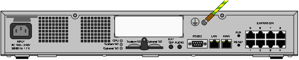
IP500 V2 Control Unit
On IP500 V2 control units the ground point is located above the RS232 DTE port.
External Expansion Modules
On expansion modules, the ground point is a 4mm screw located towards the right on the rear of the module.
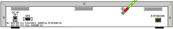
•On some older modules, the dedicated ground point screw is not present. In those cases, the top-center cover fixing screw (3mm) can be used as an alternative ground connection point. A toothed washer should be added to ensure good contact.