These notes relate to the IPO IP500 WALL MNTG KIT V3 (SAP 700503160). This kit can be used to wall or rack mount IP500 V2 control units and IP500 external expansion modules.
The kits includes all components necessary for wall mounting onto a plywood surface. The use of the cable covers is optional.
In addition to the existing environmental requirements for an IP Office system, the following additional requirements apply when wall mounting a unit:
•The wall surface must be vertical, flat and vibration free. Attachment to temporary walls is not supported.
•Only the screws provided with the mounting kit should be used to attach the brackets to the control unit or expansion modules.
•The installation must be done by a service person.
•Ensure that the system has been shut down and power has been removed from all the units. Shut down the system using a shutdown command and then remove the power. Do not simply remove the power.
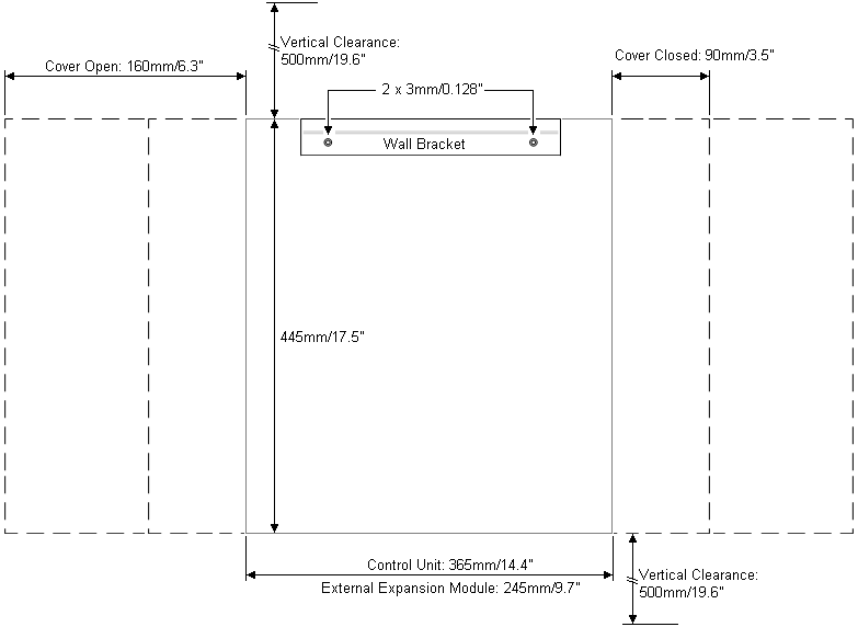
•A suitable plywood mounting surface of at least 1m x 1m x 19mm (39” x 39” x 0.75”) is required. If an expansion box is being mounted as well a plywood mounting surface of at least 1.2m x 1.2m x 19mm (48” x 48” x 0.75”) is required.
•A minimum of 6 x 45mm long 5mm/6mm ( 1.75” #10/#12) pan head screws must be used to secure the plywood to the wall studs.
•The supplied 20mm long 4mm (#8 ¾”) wood screws must be used to secure the brackets to the plywood mounting surface
•The installation must be done by a service person only.
•For control units, the mesh flame screen must be installed on the bottom edge of the control unit before mounting. The flame screen attaches to the outside of the control unit.
•Ensure that the system has been shutdown and power has been removed from all the units. Shutdown the system using a shutdown command and then remove power. Do not simply remove the power.
•Full installation instructions are included with the kit.