|
Any external expansion modules should be connected to the control unit before power is applied to the control unit. Ensure that modules are attached in the order that matches the planned or pre-built configuration. External expansion modules connect to the IP Office control unit using an expansion interconnect cable. Each module is supplied with an expansion connect cable and a power supply unit. An appropriate locale specific power cord for the power supply unit must be ordered separately. |
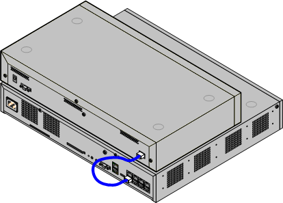
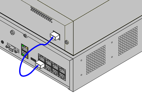
•Each external expansion module is supplied with a blue 1 meter (3'3'') expansion interconnect cable. This cable must be used when connecting to expansion ports on the rear of a control unit.
•When connecting to expansion ports on an IP500 4-Port Expansion card, a supplied yellow 2 meter (6'6") expansion interconnect cable can be used in place of the supplied blue cable. 4 Yellow cables are supplied with the IP500 4-Port Expansion card.
•! IMPORTANT: You Must Switch Off the Control Unit Before Adding, Removing or Swapping Components
Base cards, trunk cards and external expansions modules must only be removed and added to an IP Office system when that system is switched off. Failure to do so will result in the new component not loading the correct firmware and not operating or not operating correctly. This applies even when swapping like for like components.
Installation Requirements
•o Installation space either on or under the existing IP Office control unit. See Rack Space Requirements for the positioning of multiple stacked modules.
•o Switched power outlet socket.
The power outlet used must include a switch and in cases where the power cord includes an earth lead, that outlet must have a protective earth connection.
•! Important: External Expansion Module Power
In order to be detected and operated correctly, external expansion modules must start before the IP Office control unit. Normally this achieved by connected all expansion modules to the same power strip as the control unit. The control unit applies a short delay to its own start-up process to ensure that expansion modules powered on at the same time as it are detected.
•o Available EXPANSION port on the control unit.
•o Grounding Requirements
•o Functional Grounding
Connection of a functional earth is:
•o Recommend for all modules.
•o Connection of a functional ground is mandatory for Analog Trunk modules.
•o Protective Grounding
Connections of a protective ground via surge protection equipment is:
•o Mandatory for Analog trunk modules in the Republic of South Africa.
•o Mandatory for Digital Station and Phone modules connected to out of building extensions.
•o Mandatory for Digital Station V2 and Phone V2 modules.
Tools Required
•o IP Office Manager PC.
•o Tools for rack mounting (optional).
Parts and Equipment Required
•o External Expansion Module.
Each module is supplied with a suitable external power supply unit and a 1m blue interconnect cable. 2m Yellow interconnect cables are supplied with the IP500 4-Port Expansion card and should only be used with that card.
•o Power cord for the power supply unit.
•o Rack mounting kit (optional).
•o Wall mounting kit (optional - IP500 external expansion modules only).
•o Cable labeling tags.
Procedure
1.External expansion modules should not be attached to a control unit that has power. If adding a new module to an existing system, shutdown the system.
2.If the IP Office system is being installed in a rack, attach the rack mounting kit to the expansion module.
3.Attach the external expansion module's power supply but do not switch power on.
4.Connect the expansion interconnect cable from the module's EXPANSION port to the EXPANSION port on the control unit.
•Note
It is recommended to connect modules from port 1 upwards, using each port in sequence.
5.Make careful note of the port used and include this detail on the cable label and any other system records.
6.Attach any other external expansion modules being added.
7.You can now attach the grounding cabling for the external expansion modules.
a.Once the expansion modules are connected and grounded you can start the system. Ensure that the external expansion module's are started before the control unit.